

From Idea to Product – The Project Flow
From Idea to Product – The Project Flow

Lorenzo Martini, 01/05/2026
Anyone with experience in the electronics world knows how deceptive it can be to rely entirely on datasheets. The reality of the lab — and even more so the reality of production — always has a few surprises in store. As we’ll see in a future article on analog-to-digital converters, the gap between ideal specifications and real-world performance can be surprisingly wide. This principle extends to the entire development process of electronic systems, particularly mixed-signal ones. Think of a seemingly simple circuit: an op-amp with a gain of 100. On the datasheet everything looks perfect: low offset, high CMRR, excellent thermal stability. Yet once implemented on the board, you might discover unexpected drift, unforeseen oscillations, or noise levels much higher than budgeted. Why? The real component interacts with a real world full of parasitic capacitances, leakage currents, non-ideal resistances, and electromagnetic interference.
This distance between theory and practice isn’t an isolated problem — it’s an intrinsic feature of every electronic project. Bridging this gap requires a methodical, systematic, and above all realistic approach, one that accounts not only for the laws of physics but also for the imperfections of the real world.
The path from concept to reality
Ideation and Requirements Definition: Laying the Foundations
Every electronic project has to start with a clear understanding of the problem being solved. It’s like preparing the ground before building a house: if the foundations are weak, the whole building is at risk. During this phase, the project team should dive deep into analyzing the needs of the customer or the market. It’s not enough to gather vague statements like “it needs to be fast” or “it needs to use little power.” You have to quantify: how fast? How much power? Under what conditions? For how long?
Let’s take a concrete example: the development of a wireless environmental monitoring system. It’s not enough to say it needs to measure temperature and humidity. We need to specify the operating range (-20 to +60 °C?), the required accuracy (±0.5 °C?), the sampling rate (every minute?), the battery life (a year?), the transmission range (100 meters?), and so on.
This quantitative definition of requirements gives us an objective benchmark against which to assess project success in later phases. It’s also the perfect moment to set priorities: in case of conflicts between requirements, which ones are negotiable and which aren’t?
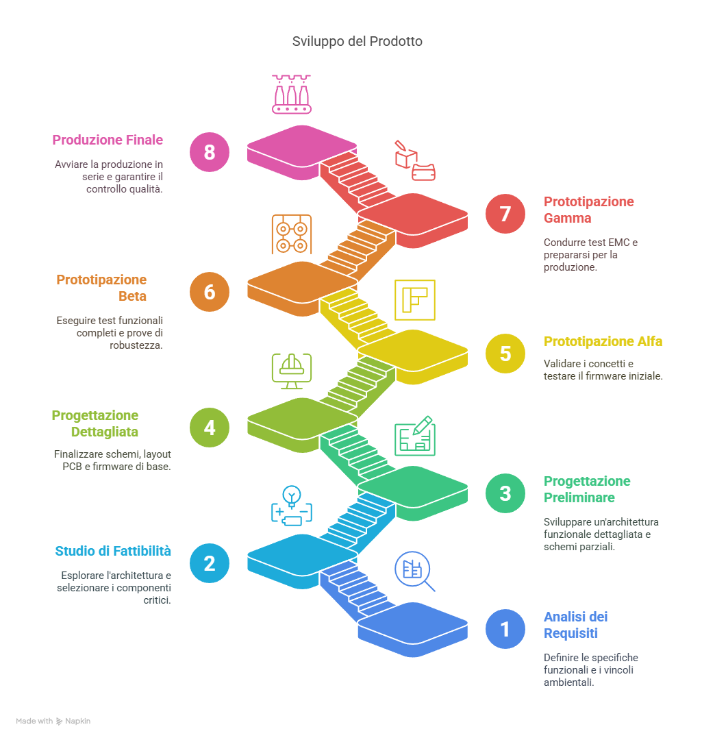
Once requirements are clear, it’s time to check whether the idea is technically feasible and economically viable. The feasibility study is the bridge between “what we’d like to do” and “what we can realistically do.”
In this phase we explore available technologies, evaluate different architectural solutions, and carry out preliminary experiments and simulations to validate the most critical operating principles. We might discover, for instance, that the humidity sensor we had in mind doesn’t work well at the low temperatures required, or that the chosen wireless technology doesn’t provide the coverage needed in environments with obstacles.
An aspect that’s often underestimated but crucial is early consultation with potential suppliers. I’ve seen too many projects where the team designed a circuit around components that later turned out to be unobtainable, or with lead times incompatible with the project schedule. In today’s environment of semiconductor shortages, tariff wars, and supply chain instability, this kind of verification has become even more decisive.
I remember a project several years ago where we had picked a microcontroller perfect for our application, only to discover months into development that it had limited availability with a 52-week lead time. A quick call to the distributor would have saved us a costly redesign. The outputs (also called deliverables) of these preliminary phases can include:
- Circuit or thermal simulations
- Proof of concept on breadboard or development board
- Decision matrices for selecting key components
- Preliminary risk analyses (FMEA, Fault Tree)
System Architecture: a Map to Find Your Way
 With feasibility confirmed, we can move on to defining the system architecture, which represents the fundamental structure of our product. This is where we decide how to split the system into functional blocks, how those blocks will communicate with each other, and how they’ll manage shared resources like power and data.
In a mixed-signal system, a key architectural decision concerns the partition between the analog and digital domains. Where do we place the A/D and D/A converters? Which part of the processing should be analog and which digital? These choices have profound implications for performance, power consumption, and system complexity.
Take an audio system, for example: we could implement analog filters before A/D conversion to reduce noise, or opt for immediate conversion followed by digital filtering. The first approach might give a better signal-to-noise ratio; the second offers more flexibility and precision. The choice will depend on specific requirements, cost constraints, and the skills of the design team.
Multi-level Prototyping: a Progressive Approach
Prototyping is the moment when ideas take physical form and we begin to confront the real world. Adopting a multi-level approach lets us manage risks and optimize resources, addressing the biggest issues in the earliest prototypes and progressively refining the design.
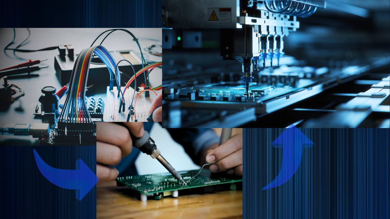
The Alpha prototype is the first concrete step. The goal isn’t to build a complete product, but to verify key concepts and the most critical functions. It might be implemented on breadboard, on rudimentary PCBs (perhaps produced in-house), or using development modules — with components that are easy to source and handle even if they’re not optimal for final production. This prototype, fast and inexpensive, lets us verify pinouts, power rails, critical signals, communications, and a microcontroller’s peripherals. In our environmental monitoring example, the Alpha prototype might focus on validating the temperature and humidity sensor under various environmental conditions, or on verifying battery life under different power management modes. The Alpha prototype is usually the output of preliminary design, which — for projects that aren’t excessively complex or structured — can coincide with the feasibility study and concept design phase.
With the Beta prototype we take a significant step forward. We now implement all the main functions on dedicated PCBs, though still with margin for modifications and adjustments, with the goal of verifying the complete functionality of the project, the integration of the various subsystems, and the interfaces between them. This prototype follows detailed design and enables its validation.
The Gamma prototype, or pre-production prototype, represents the last stage before actual production. The design is now very close to final, and the goal is to assess manufacturability and the performance of the complete system. A small batch is built using production processes similar to the final ones in order to identify any assembly or testing issues. The pilot batch is also useful for verifying product uniformity and any performance drift between individual units.
Throughout this evolution, we need to run an increasingly thorough set of tests:
In the EVT (Engineering Validation Test) phase we verify that the design meets the basic technical specifications. DVT (Design Validation Test) involves a more in-depth evaluation of all parameters under various conditions, while PVT (Production Validation Test) confirms that the product can be manufactured with adequate quality and yield.
This progressive approach lets us identify and fix problems when the cost of changes is still manageable. A bug caught during the Alpha phase usually costs about one-tenth of what it would cost to fix in production.
Detailed Design and Implementation
With the architecture validated through the initial prototypes, we can proceed to detailed design of both hardware and software/firmware. In hardware design, component selection takes on a crucial role. It’s not just about finding the chip with the best specs — you also have to consider availability, life cycle, cost, and reliability. Personally, I prefer components that are slightly oversized but have a long track record of reliability, rather than the latest thing fresh off the market.
Schematic capture requires attention not only to functional connections but also to protection, filtering, and robustness. A good design always includes protection circuits against reverse polarity, overvoltage, and electrostatic discharge, even when they’re not explicitly required in the specs — obviously as long as there aren’t extreme cost constraints where even a dime can make a difference.
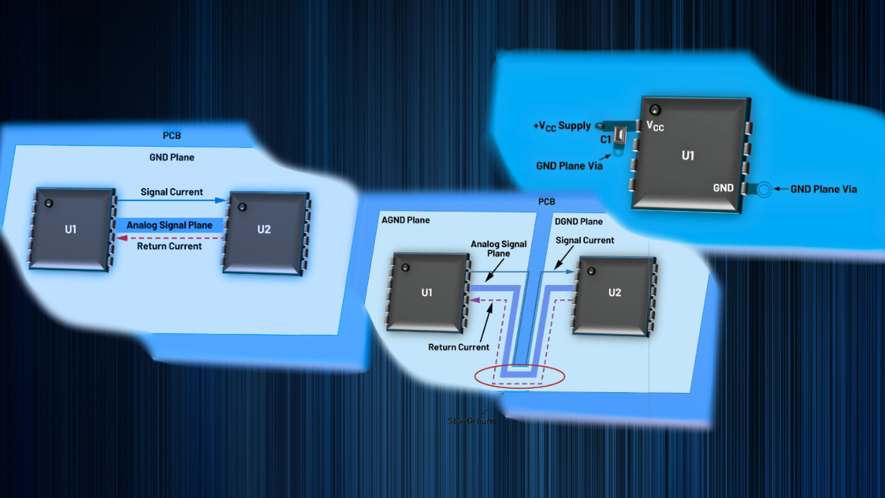 PCB layout deserves a special mention, especially in mixed-signal projects. Separating analog and digital sections, carefully routing critical signals, and managing ground and power planes — these are all aspects that can make the difference between a mediocre product and an excellent one. You’ll find many articles on the blog dedicated to this topic.
In parallel with hardware design, we develop firmware and/or software. A modular software architecture makes testing and future maintenance easier. Hardware drivers should abstract the implementation details of components, allowing them to be swapped out without affecting the higher layers of the software. Processing algorithms often represent the real added value of the product. In our environmental monitoring system, we might implement sensor-fusion algorithms to improve measurement accuracy, or data compression techniques to optimize wireless transmission.
The deliverables of detailed design are:
- Complete and up-to-date technical documents (schematics, layout, firmware, mechanics)
- Production files (PCB fabrication specifications, Gerber files, pick&place, BOM, and where applicable inserting the bill of materials into the company ERP)
- Preliminary technical manuals (assembly procedures, usage instructions, test instructions)
Test and Validation: The Acid Test
Rigorous testing is the key to bridging the gap between theoretical specifications and real-world performance. Too often I see projects where testing is treated as a marginal activity, something to rush through in the last few weeks before delivery. Nothing could be more wrong. Testing should be planned from the very beginning and integrated into every phase of the development cycle.
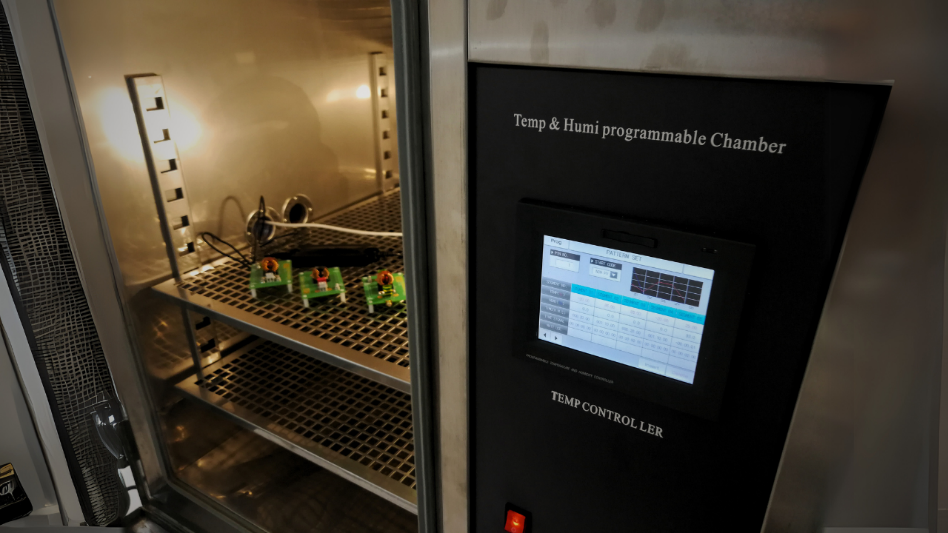
Functional tests verify that the system does what it’s supposed to do under nominal conditions. Performance tests quantitatively measure key parameters like accuracy, speed, and power consumption. Environmental tests evaluate the system’s behavior under various conditions of temperature, humidity, vibration, and exposure to electromagnetic disturbance. Particularly important are the reliability tests, which simulate aging and intensive use of the product. Techniques like HALT (Highly Accelerated Life Testing) and HASS (Highly Accelerated Stress Screening) let us identify weaknesses and latent defects before the product reaches the customer.
One approach I’ve always found useful is “devil’s advocate testing”: actively trying to make the system fail by trying unusual input combinations, non-standard operating sequences, or conditions at the edge of the specs. This approach uncovers vulnerabilities that standard tests might miss.
Don’t forget — the circuit has to be produced
The transition from prototyping to series production is more a transformation of the process than of the product itself. A perfectly working prototype doesn’t automatically guarantee a successful production run.
Industrialization starts with optimizing Design for Manufacturing (DfM). This means adapting the design to make assembly easier, reduce the chance of errors, and minimize costs. It might mean standardizing components, eliminating ambiguous orientations, or simplifying complex soldering processes.
Equally important is Design for Testing (DfT). Incorporating test points, dedicated connectors, and self-diagnostic functions into the product massively simplifies production testing, reducing time and cost. In our monitoring system, we might add a test mode that checks all the sensors and automatically calibrates the device.
 As already mentioned, these topics have to be addressed early by involving the assembly and test service suppliers and the company people who specifically deal with these matters, like department heads and process engineers.
Production documentation must be clear and complete: a detailed BOM, precise assembly instructions, unambiguous test procedures. I’ve seen many problems born from someone assuming the line operator would just “figure out” how to correctly assemble a critical component.
An aspect often overlooked is training the production staff. Taking the time to explain not just the “how” but also the “why” of certain procedures can make the difference between a robust manufacturing process and one riddled with recurring problems.
Cost Optimization: A Continuous Process
Cost optimization isn’t a one-off activity — it’s a process that runs through the entire development cycle. In every phase there are opportunities to improve the project’s economic efficiency without compromising quality. In the design phase, strategic component selection can have a huge impact on final costs. Focusing on one function, one component, one detail should never cause you to lose sight of the overall system — just as evaluating the cost of a single component shouldn’t replace an effort to assess the Total Cost of Ownership (TCO). Choosing a microcontroller slightly more powerful than strictly necessary, for example, might seem wasteful, but if it lets you eliminate other dedicated chips, the total cost may end up lower. Likewise, investing in thorough simulations can reduce the number of hardware iterations, leading to significant savings.
During prototyping, a progressive approach lets us invest resources where they’re really needed. It makes no sense to build an aesthetically perfect pre-production prototype if we’re not yet sure the core functionality works. Resources saved in the early phases can be invested in more thorough testing on more mature prototypes.
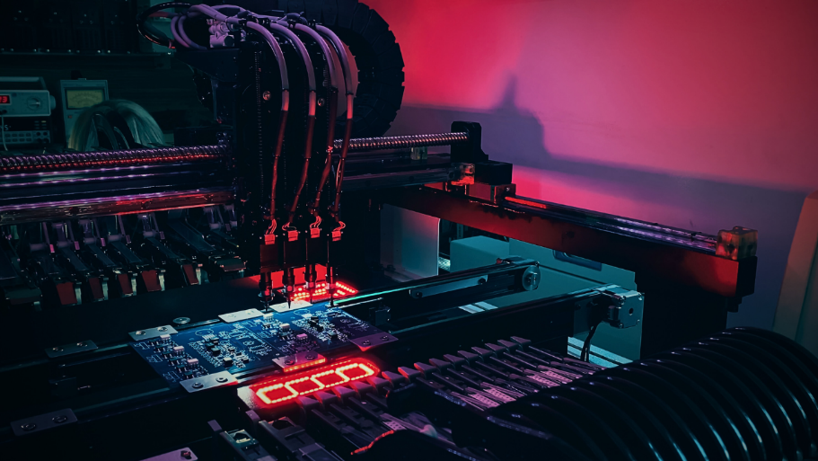
In production, test automation and process optimization can drastically reduce unit costs. An initial investment in automated test equipment pays for itself quickly as volumes grow. Even small process improvements, like reducing setup times or minimizing scrap, can translate into significant long-term savings.
Best Practices for Successful Mixed-Signal Projects
I’ve focused on mixed-signal microcontroller-board projects because the experience I’ve accumulated, especially on this kind of project, has taught me some valuable lessons that I’d like to share. Clearly, many of the considerations here — which in the end are just common sense — can be extended to products of various kinds.
In analog design, it’s essential to plan for adequate safety margins. An amplifier that works perfectly with a gain of 100 in the lab might saturate in production due to component tolerances or different environmental conditions. Sensitivity analysis helps us identify critical parameters to focus on, while Monte Carlo simulations can anticipate the effect of variations in real components.
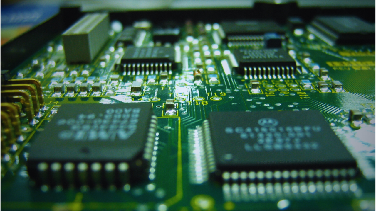
PCB layout is probably the most critical aspect of mixed-signal systems. The separation between analog and digital sections must be clean, with dedicated ground planes connected at a single, well-defined point (star-point grounding). Power-supply filtering must be distributed, with bypass capacitors placed as close as possible to the supply pins of sensitive components. The PCB stack-up is also fundamental to give the design its best shot at success (you can read more on this in the articles “Arranging the layers of a PCB” Part 1 and Part 2).
The interface between the analog and digital domains needs particular attention. Analog signals should be properly buffered before being exposed to digital loads. Digital clocks need to be kept away from sensitive analog lines, and when that’s not possible, effective shielding techniques must be used.
As for testing and validation, I can’t emphasize enough the importance of a complete characterization under real-world conditions. Lab tests under ideal conditions are a good starting point, but the product will run in the real world, not in a lab. Tests that evaluate performance under extreme operating conditions (min/max temperature, min/max supply voltage, etc.) can reveal problems that would stay hidden under nominal conditions.
One final tip, which may sound obvious but which I often see ignored: document everything. This is also advice for business owners and decision-makers: documentation is a cost to be budgeted into the project, not a quick hour of drudgery to knock out before diving into the next task. Document the reasons behind design choices, the simulations performed, the test results, the problems encountered, and how they were solved. This documentation not only makes future maintenance of the product easier, it’s also the company’s real knowledge asset — invaluable for future projects and for making sure whoever takes over maintenance can actually do it.
Final Thoughts: The Art and Science of Electronic Development
Developing mixed-signal electronic systems is a fascinating blend of rigorous science and practical art. Science gives us the physical laws, the mathematical models, and the analysis techniques. The art lies in knowing when and how to apply those theoretical tools to the imperfect and unpredictable world of reality. Success in this field requires a systemic view that considers the entire product and its life cycle, not just individual components or isolated development phases. It also requires a balance between technical perfection and pragmatism: the perfect project that never ships is no use to anyone. That’s why the project activity needs to be overseen by someone who can weigh the performance/cost trade-off. Progressive prototyping, rigorous testing, and thorough documentation are the pillars of a robust development process. But equally important are effective communication among team members, early collaboration with suppliers and production, and realistic management of all stakeholders’ expectations.
Ultimately, the goal isn’t to create the absolutely perfect system, but the one that best meets the customer’s specific requirements, within the given time and budget constraints, with the expected quality and reliability. In a world of rapid technological change, staying up to date on new technologies and methodologies is crucial. But even more important is consolidating the fundamental principles that stay valid regardless of specific technologies: methodological rigor, the systemic approach, attention to detail, and a passion for quality. These are the real secrets to bridging the gap between theory and practice, between ideal specifications and real-world performance, between initial concept and successful product.